Energy Island Building, Marine Design Proposal, Sea Architecture, Wave Power
Energy Island : Sustainable Maritime Building
Sustainable Maritime Architecture – Generation
22 May 2008
Energy Island Design
Architects: Dominic Michaelis + Alex Michaelis
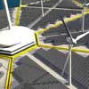
Aerial view of Energy Island Module Centre, showing Otec Electric power and desalinated water production plant room, with base of pole of surface furnace receiving all radiation falling on roofs of factory / office / greenhouse buildings crowned by heliostat mirrors following the sun, aerogenerators on the platform deck.
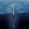
Alternative to platform-mounted aerogenerators, where generators are placed at a suitable distance from an inhabited platform. These aerogenerators have a prolonged tubular shaft below sea level, the bottom part of which is ballasted, so that the aerogenerator, independently moored, can’t be blown flat, since all pressure on the blades is resisted by the moment created by the shaft’s displacement from the vertical.
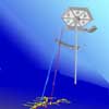
Geotec: in this application, the energy island is placed above a geothermically active area, in this case, a visible volcanic linear eruption along a tectonic fault line. Octagonal turbogenerators are lowered by underwater rovs, containing enough air to make them buoyant, so that they can be anchored at a reasonable distance above the fault. They will be using water at 300C or more as the heat source, umbrellas along the line brining more hot water. The condensors use cold water at 5C drawn in by long buoyant tubes. Generated electricity is cabled up to the Energy Island.
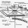
Energy Island perspective view of a single hexagonal module showing different energy converter systems and overall functional disposition.
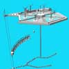
Energy Island perspective view, showing the floating platform hexagonal module surrounded on its wave front energy converters, in the lee of which is the protected island, and behind that, a harbour serving the island. To the left is a platform for staff housing, and at its left extremity, a geothermal drilling rig, to which rise two electric cables, one from the sea current turbines, another from a series of turbines lowered down to recover geothermal energy from geological fault lines resulting in very high water temperatures capable of efficient electricity generation.
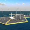
2 Otec Energy Islands with additional module for high energy industrial process factory, or for leisure combined with education facilities.
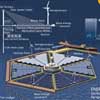
General view of Energy Island with overall functional diagram and open cycle Otec system diagram.
Images from Dominic Michaelis May 2008
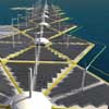
View along axis of 8 Otec modules supplying 2000 MWe, the equivalent of a very large nuclear power station, and 2400 million litres of desalintaed water per day, sufficient for 8 million US households.
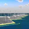
Aerial view of linear array of 8 x 250 MWe Energy Islands forming a 2000 MWe power plant, possibly electrolysed to hydrogen fuel, and a desalination plant of 2.4 million cubic meters per day capacity (total desalination capacity of the Kingdomof Saudi Arabia – 3 million cubic meters per day).
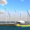
Sea level view of 8 Otec 250 MWe Energy Islands with 2000 MWe power output.
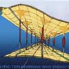
The Lilypad twin membrane wave energy converter consists of an upper floating flexible membrane following the wave motion, provided on its udnerside with load distributing flanges taking upward loads to a number of linearly disposed fixation points to which are attached arrays of hose pumps. Hose pumps operate on the principle that as they are elastically elongated from their original large diameter cylindrical shape, they gradually reduce in volume, pressurising the working fluid within them.
At their base, the hose pumps are fixed to load distribution cables which are in turn fixed to the bottom membrane, which is both weighted and valved, so that it will resists upward movement as it is pulled up by the passing wave, flexible flaps closing against a mesh below them.
After the wave has passed, the bottom weighted membrane sinks downards by gravity, the valves opening upwards, and returns to its initial position, ready for the next cycle.
The hose pumps extend as the wave passes, expelling working fluid, normally seawater, that runs to and along high pressure pipes to a hydraulic generator. Electricity is generated typically at 65% efficiency by a hydraulic trubogenerator. This mode prevails till the hose pump is partially or fully extended by the wave crest. As the wave passes, the upper membrane descends, gradually releasing pressure on the hose pump, which elastically returns to its shorter and larger cylindrical shape, drawing in seawater through a one way valve. This allows the lower membrane to descend to its original position, ready for the next upward stroke.
The membranes run perpendicularly to prevailing significant wave direction, the size and length of hose pumps being related to wave length and amplitude. Spacing of hose pumps and width of marine platform structure.
Marine platform structures are designed to resist the impact of waves, which vary in intensity from location to location. They must be capable of resisting the strongest storms, and in some areas, rogue waves that can reach twice the height of the strongest normal waves of that location.
15 meter high waves are known to occur in many parts of the oceans, and the corresponding rogue wave, occurring where currents are strong, which may be a 1 in 1000 year chance, will reach 30 meters, the height of a 10-storey building. In other more fortunate areas, where there are no currents and no strong winds or cyclones, it might be 5, 10 tor 20 meters high.
A marine platform cannot be designed as a floating raft, because in very heavy seas, its inertia will be such that it will not have time to react to high wave onslaught, and risks being submerged.
The proposal presented is a minimal structure based on tetrahedral geometry occupying the space where the wave impact and its energy are deployed, the structure transferring to the platform the forces from the buoyancy tanks that are in “protected” waters, and insure the platform buoyancy, allowing the structure to rise or to descend according to the amount of air with which they are fully or partially filled.
The top of the buoyancy elements is shaped to resist the wave impact, allowing the tetrahedral structure to be reduced in height. The shape also makes it easier for the overall structure to rise if there is some unforeseen upward pressure on the underside of the deck.
This section through two flexibly jointed juxtaposed marine platforms illustrates the structural principle adopted, showing the upper tetrahedral structure designed to be “transparent” to oncoming waves, the buoyancy elements taking the point loads from the structure above, and transferring the forces they exert through the tetrahedral structure to the deck above. The buoyancy elements can be increased in depth according to the loads carried by the deck, the tetrahedral structure needing to be reinforced accordingly.
ENERGY ISLAND
“The sea, the sea, ever renewed…” Paul ValÈry
The Seas reveal many vast and diverse energy sources which are too often considered individually, for instance the energies of wind, wave, sea currents, tides, solar energy including marine photosynthesis, geothermal and ocean thermal differential energy. Also, some renewable energy sources, often converted on land, can be more efficiently sea based, wind energy being a typical example, where land features reduce its intensity and limit its locations. Land based wind farms have proved themselves to be visually unacceptable to many, whilst solar farms often occupy too much valuable land.
To best profit from the many renewable energy sources available at sea, the concept is to create an “Energy Island” which would take the form of a floating platform designed to harvest all usefully available energy sources available to it, none acting in isolation, but all being brought together so that each acts to complement the other, adding its contribution to the whole.
A typical “Energy Island” may be of hexagonal shape plan, of any size up to 500 meters along its shorter axis, having a surface area of 22 hectares, the hexagonal shape allowing islands to be joined in cluster or linear modes according to planning intents. Such an island is designed to provide a total of 250 MW, with 1/3 of the energy being contributed by ancillary sources and 2/3 by OTEC. It is designed to intercept the following:-
Wave Energy. On the winward sides, the island features linear wave energy converters, WECs, which can take the form of one of the many different systems invented, whether the oscillating water column, the “lagoon”, or another system, these converters playing two parts, firstly protecting the island from the heavy seas, and then providing hydraulic energy to the platform to induce fluid flows, or to generate electricity. One new departure is the all flexible “twin membrane” Lilypad WEC which Energy Island is promoting.
Wind Energy. Wind energy at sea is at its strongest, unaffected by land masses. The “Energy Island” module is provided with six large aerogenerators, three being at a lower level to intercept the sea hugging wind flow, whilst three are higher to capture the upper wind flows, the hydraulic masts being able to adjust the heights of the aerogenerators to best harvest the wind potential from different directions.
If they are unacceptable on the island because of electromagnetic radiation, they can be floating ballasted structures moored independently sufficiently far from the island.
Sea Currents. Sea currents are powerful energy sources and can be interceped by “nets” made up of linear arrays of cowled turbine units held up below the “Energy Island” by moored buoys between which they are stretched, each unit having its own separate flotation buoy, the array taking up a slight catenary curve under pressure from the current, the main moored buoys having the capacity to be relocated below the island to accommodate shifts in the current direction. The array is positioned at a depth where it is little affected by wave energy which is mostly expressed down to a depth equivalent to 1/6 ths of its wavelength.
Marine turbines can be fitted to the base of the support platform.
Solar Energy. Solar energy at sea level is at 950 Watts/sq.m, when the sun is directly overhead, and can be collected in many different ways. The hexagonal plan of the “Energy Island “ suggests the possible use of a centrally located “power tower” furnace onto which are focussed a field of orientable heliostats or mirrors, giving furnace temperatures around 900_C which allow relatively efficient electricity generation, with the possibility of waste heat recovery above the boiling point of water, which can be used and stored to assist thermal processes that are part of Ocean Thermal Energy Conversion.
OTEC Electricity generation OTEC in tropical waters is the main electricity generation source, with a combination of closed and open cycle systems for efficiency at different temperatures combined with desirable sea water distillation for a number of on board activities. All waste heat from the solar farm is used to enhance a working fluid temperature, the surface water being channelled to the centrally located power plant along the six radial canals going to the outside apexes of the hexagon where floating dark membrane solar collectors optionally enhance the inlet temperatures. All warm and cold water pumping being carried out uses the ancillary energy sources deployed, these measures to increase Carnot efficiencies and to prevent OTEC from wasting the energy it is itself generating.
OTEC seawater desalination OTEC, in certain configurations, will produce vast amounts of desalinted water, often proportional to the electric power generation capacity. In the open cycle mode, OTEC will produce 1,2 million litres of desalinated water per MW. This effectively makes OTEC plants act as both power stations and desalination plants, effectively doubling their value.
Geothermal Energy The Energy Island can be purposefully located above geothermal energy resources. These can be tapped by drilling for hot aquifers or pumping water through fissured hot rocks . Alternately, hot volcanic flumes can produce water at 300_C that cannot boil because of the high pressure, but into which can be lowered turbogenerators using the cosiderable temperature difference from water drawn by arms reaching out for nearby cold water, unaffected by the flumes, thzat often follow linear tectonic faults.
Apart from its electric and desalinated water contributions, the “Energy Island” is designed also to produce :-
Hydrogen. Because of the fluctuation of renewable energy resources, an energy storage system is required. The “Energy Island” relies on a hydrolysis plant to produce stored hydrogen and oxygen, part of which can be used by fuel cell technology as necessary to balance the power output, matching it to requirements both external and internal, and part being used as a fuel that can , in some cases be tankered or pipelined to other destinations, when the electricity produced is not totally used by cable links to nearby destinations. The “Energy Island” will also produce a base for:-
Controlled Environment Agriculture (CEA) and Mariculture.
In tropical latitudes, greenhouses need to be protected from the sun, a role performed by the heliostats, and well ventilated or evaporatively cooled. The 22 hectare platform can therefore be used for CEA, using part of the distilled water from the open OTEC cycle for hydroponics. If the floor is trellissed, light can reach the seawater below, where pens can contain various forms of marine life below.
Harbours and Housing. On the leeward side of the island or islands, The “Energy Island” needs to provide housing for staff , social facilities, workshops and harbours. Cold wter at 5_C can be used for air conditioning.
Leisure and Tourism Energy Islands can be dedicated to energy self sufficient holiday destinations, where also fish, fruit and vegetables are produced “on board”, the islands having the advantage of being located as desired close to attractions that can be reached by boat, by helicopter, or by air, if a short landing strip is provided.
The “Energy Island”, intercepting many diverse renewable energy sources, brings their converted powers together in the most efficient way to provide electricity for the grid, and, by hydrolysis, hydrogen fuel for transport to nearby or distant population centres, where it can be used efficiently by fuel cell technology.
The “Energy Island” can become a major supplier of electricity and hydrogen fuel for a pollution free society, and liberate the world from the perils of nuclear power generation, and from its political, economic and polluting dependence on dwindling fossil fuels, providing vast amounts of desalinated water as a bonus.
The “Energy Island” constitutes a new departure, all the more necessary because of the visible and invisible, but predicted signs of universal pollution and global warming, and the frightening fact that world energy use is expanding exponentially, having doubled in the last thirty years.
Action is needed to bring about change, promote a new fuel and turn the tide.
Maritime Architecture
Samundra Institute of Maritime Studies
Malta Maritime Authority Centre
National Maritime Museum London
Seas of the World, Maritime Concept Design

picture from architect
Eco Architecture
Comments for the Energy Island page welcome
Website: www.energyisland.com
